Wednesday, November 30, 2011

Crazy compiler bugs, AVR Studio's avr-gcc commands explained, and makefiles

[Edit: solved, the error was in the fab hello world makefile line
$(OBJCOPY) -j .text -O ihex $(PROJECT).out $(PROJECT).hex
To fix, add -j data or drop the -j option altogether)
See http://www.micahcarrick.com/avr-tutorial-digital-output.html. also, man avr-objcopy.
What was actually happening was in one example the compiler replaces the code with the array data and then loads it into the microcontroller, while for the other example it loads the compiled code into the micro, and in both cases the constant array never makes it into the microcontroller.]


The surface symptoms of crazy compiler bug which appears to eat variables (NOT an optimization issue! -- check out this awesome thread for more about that http://www.avrfreaks.net/index.php?name=PNphpBB2&file=viewtopic&t=97382 )
Me: I'm getting bugs where the exact symptom in simplest form is

=========
void light_led(char led_num) {
   DDRB = led_dir[2];
   PORTB = led_out[2];
}
void main(void) {
   while (1) {
      light_led(2); //obviously I am ignoring the argument given here
   }
}
=========
works as expected but
=========
void light_led(char led_num) {
   DDRB = led_dir[led_num];
   PORTB = led_out[2];
}
void main(void) {
   while (1) {
      light_led(2);
   }
}
=========
doesn't. (tested and doesn't work: char, volatile char, int and now int8_t and uint8_t).

Based on this code: https://github.com/benbrandt22/TinyLife5/blob/master/TinyLife5.c
(full file here: https://github.com/nouyang/pov-yoyo/blob/master/v0.1.45.c)

Yes, I tried int instead if char in case C arrays wanted int indices. And volatile char in case the compiler was like "You, variable! You are a useless waste of memory. OPTIMIZED." (sfx notes: that should sound like RECTIFIED in Tron).

Okay, so why doesn't AVR Studio 5 Debugger work?
Turned out AVR Studio debugger is straightforward, but it doesn't work if you have a

void main (void) {}
function instead of a
int main ... (return 0; )
function.

Also, AVR Studio 5 is amazing. I can peer at all the DDRB and PORTB and all the pins -- even with an oscilloscope I would need like 8 arms to do this.
Oh right, back from worshiping AVR for making AVR Studio freely available (the Gobsmacking Glory of which is only slightly diminished by my sadness that it's not open-source / doesn't run on linux (haven't tried WINE yet)) and on to compiler issues.

Re: linux avr toolchains, Pranjal Vachaspati, hallmate and 2014, in yet-another-spam-thread-I-started, writes:
If you're using AVR eclipse (and I strongly recommend you do, as AVR development has way too many steps to comfortably manage manually), make sure you change the build target from "Debug" to "Release" or else it won't create the appropriate binary. Also if you're not using AVR eclipse it's awesome! http://avr-eclipse.sourceforge.net/wiki/index.php/The_AVR_Eclipse_Plugin

In the meantime, I will continue my terrifying toolchain of Desktop > AVR Studio > Compile > attach *.hex file to email > Netbook > download file > run avrdude > Debug in AVR studio > ... =/ Maybe AVR Studio works with Wine.

I grabbed the avr-gcc commands from the terminal output at the bottom of AVR Studio 5, edited the filenames, and used it to compile C code on ubuntu. (Note that choosing "Release" uses -Os, full optimization, while choosing "Debug" uses -O0, no optimization. For my code this results in 3 kilobytes flashed versus 150 bytes! -- 3kb = almost 90% of available mem on attiny45)

I'm writing some C code for the attiny45 microcontroller for how to make anything,  and I'm debugging a problem where for the exact same C code,  AVR Studio creates a happy .hex file but the class-derived makefile creates a "I'm-going-to-half-work-and-drive-you-crazy-debugging" .hex file (see C code above for the symptoms).

 ~~~AVR Studio commands
avr-gcc -funsigned-char -funsigned-bitfields -Os -fpack-struct -fshort-enums -g2 -Wall -c -std=gnu99  -mmcu=attiny45   -MD -MP -MF"v0.1.45.d" -MT"v0.1.45.d" -o"v0.1.45.o" "v0.1.45.c"
avr-gcc -mmcu=attiny45  -Wl,-Map=v0.1.45.map -o v0.1.45.elf  v0.1.45.o
avr-objcopy -O ihex -R .eeprom -R .fuse -R .lock -R .signature  "v0.1.45.elf" "v0.1.45.hex"
avr-objdump -h -S "v0.1.45.elf" > "v0.1.45.lss"
avr-objcopy -j .eeprom --set-section-flags=.eeprom=alloc,load --change-section-lma .eeprom=0 --no-change-warnings -O ihex "v0.1.45.elf" "v0.1.45.eep" || exit 0
avrdude -p t45  -c usbtiny -U flash:w:v01.45.hex
~Results  as run on Ubuntu 11.10 in 435 bytes .hex file / 146 bytes flashed. And results in a bunch of magical files.

~~~Class-derived Makefile
avr-gcc -mmcu=attiny45 -Wall -Os -DF_CPU=8000000 -I./ -o ./v0.1.45.out ./v0.1.45.c
avr-objcopy -j .text -O ihex ./v0.1.45.out ./v0.1.45.c.hex;\
avr-size --mcu=attiny45 --format=avr ./v0.1.45.out
avrdude -p t45  -c usbtiny -U flash:w:v0.1.45.c.hex

~Results as run on Ubuntu 11.10 in 443 bytes .hex file / 150 bytes flashed. (it takes up more memory and it doesn't work right! :/)

So, I emailed out to the MAS.863 and one of the TAs promptly spent almost an hour writing an essay in reply. o__o Yay awesome people. Directly copied:
Brian Mayton (bmayton):

Here's what some of this means.  First, starting with the compiler command (avr-gcc).

> avr-gcc   -funsigned-char -funsigned-bitfields -fpack-struct -fshort-enums

The -f options change the behavior of the compiler.  -funsigned-char tells it that the 'char' type is by default unsigned (that is, cannot represent negative numbers, but can store numbers twice as large.)  Normally in C 'char' is signed, and if you want an unsigned one you have to say 'unsigned char'.  This flag swaps it around, so that 'char' is unsigned by default and you have to say 'signed char' if you want a signed one.  Generally, when writing microcontroller code, I very much prefer to be explicit, never assuming what the compiler is going to do.  <stdint.h> is part of the C standard library and defines types like 'uint8_t' (an unsigned 8-bit integer, same as 'unsigned char') and 'int8_t' (a signed 8-bit integer, same as 'signed char.')  I prefer these over the char, short, int, long types because I know exactly what I'm getting.

-funsigned-bitfields says that bitfields are also unsigned.  If you don't know what bitfields are, you're probably not using them.  (Most code for avr-gcc doesn't use them.)

-fpack-struct says that all structs should be packed.  (Look up C structs if you're not sure what these are.)  On some processor architectures, memory is addressed a 'word' at a time—on a 32-bit x86 processor, for example, a word is 32 bits (or four bytes) long.  The instructions for accessing a word of memory tend to be faster when the word being accessed is 'aligned' to a word boundary, i.e. its address in memory is a multiple of four bytes.  In a struct, if you were to have, for example, three fields that were each one byte long (uint8_t), and then one field that was four bytes long (uint32_t), and the beginning of the struct is aligned to a word boundary, then the 32-bit variable won't be, and accessing it will be slower than if it were.  So sometimes the compiler will insert 'padding' to make sure that all multi-byte fields in a struct are aligned to word boundaries; in this case, it might insert one byte of padding in between our three single-byte variables and the four-byte variable to push it over onto the word boundary.  Telling the compiler that a struct should be 'packed' tells it *not* to insert this padding.  On a microcontroller with limited memory, you might prefer the slower access to unaligned fields to the 'wasted' memory that padding creates, or if you're implementing a network protocol that needs the fields to be at specific locations.

-fshort-enums tells the compiler that enums (again, look this up if you don't know what they are) should be stored as a 'short' rather than an 'int'.

My guess is that it's likely one of the above flags that makes your code work, but without seeing your code I couldn't say for sure.

>   -Os

This sets the optimization level.  -Os means that the compiler should optimize to make things faster, but try to produce the smallest program possible.  -O0 means don't optimize, -O1 means some optimizations, -O2 enables more optimizations, and -O3 turns on optimizations that might also result in a larger program. http://www.avrfreaks.net/index.php?name=PNphpBB2&file=viewtopic&t=71862
http://www.societyofrobots.com/member_tutorials/node/207
>   -g2

This tells the compiler to include debugging information in the code it generates; if you use a debugger later, it uses this information to map between which instruction in the compiled program corresponds to which line of the C files.

>   -Wall

This tells the compiler to enable all warnings.  There are some warnings that aren't enabled by default (such as you defined a variable but didn't use it, there's nothing wrong with that, but it might be a mistake.)  This can sometimes help point out programming bugs that compile fine but might not be what you meant to write.

>   -c

This tells the compiler that it's going to build an object file instead of a complete program.  Object files contain compiled functions, but they're not yet 'linked' together into a complete program.  When you use a C compiler, one way to do it is to just give it all of your C files at once and have it produce a complete program all in one go (this is how Neil's example Makefiles do it).  In more complex programs, it's often useful to produce the intermediate object files first, and then link them together into the complete program at the end.  If you have lots of .c files, and only change one, then you only need to rebuild the .o object file corresponding to the .c file that changed.  For a big project with lots of code, that can be faster.

You can read more about what 'compiling' and 'linking' mean (lots of info online) if you want to get a better understanding of what's happening.

>   -std=gnu99

This tells the compiler to use the GNU99 standard.  There are a couple of different variants of C.  There's 'ANSI C' or C89 (the '89' corresponds to 1989, the year the standard was ratified.)  C99 is a newer revision to the standard that adds some extra features to the language (like being able to declare varaibles at other places than the top of a block.)  GNU99 adds in a handful of GCC-specific extensions.

>   -mmcu=attiny45

This, of course, tells the compiler what processor to produce code for.

>   -MD -MP -MF"v0.1.45.d" -MT"v0.1.45.d"

These are all dependency-tracking options, that tell the compiler to save information about which header files are used by each .c file, which can be used later to determine, if a header changes, which source files need to be rebuilt.  This is useful for large projects, but not terribly useful for small microcontroller stuff.

>   -o"v0.1.45.o"

This specifies the output filename.  Usually the convention for object files is whatever the name of the .c file was, but with .o instead.

>   "v0.1.45.c"

And finally, this is the .c file to compile.  And that's it for the compilation step.  If you had multiple .c files in the program, this would be repeated for each one.

Now, the linking step:

> avr-gcc -mmcu=attiny45  -Wl,-Map=v0.1.45.map -o v0.1.45.elf  v0.1.45.o

This also uses the avr-gcc command, but since there's no -c flag, it's going to build a complete program instead.  The linker will take all of the object files (in this case, only one) and assemble them together into a complete program, figuring out where everything fits in memory.  The object files have 'notes' in them that say things like 'here I want to call function foo()'; it's the linker's job to decide where function 'foo()' is actually going to be in memory, and replace that 'note' with the actual address for the program to jump to.  The -Wl,-Map= flag tells the linker to also produce a file that says where it's putting things, which can be helpful to reference when debugging sometimes.

The -o flag, like before, specifies the output file; for a complete program, this will be in 'elf' format.  (This is a standard format for executable programs, you can read more about it if you want.)  Finally, a list of all of the .o files to include in the program follows (in this case, again, we only have the one.)

Now some objcopy/objdump stuff:

> avr-objcopy -O ihex -R .eeprom -R .fuse -R .lock -R .signature  "v0.1.45.elf" "v0.1.45.hex"

Mostly for historical reasons, a lot of programming tools won't read an elf file directly.  Customarily, the file format that's used is Intel HEX (ihex, or simply .hex.)  (Some embedded systems also use Motorola S-record or srec files).  The objcopy command here is basically copying the compiled code from the elf file into a hex file.  It's told (via the -R flags) to ignore the .eeprom, .fuse, .lock, and .signature sections (so this hex file will basically only contain the program code, or the .text (in executable parlance, 'text' often means compiled code) section.)

> avr-objdump -h -S "v0.1.45.elf" > "v0.1.45.lss"

objdump here is generating a file with the disassembly listing of the compiled program.  This is completely unnecessary to generating working code, but sometimes looking at the disassembled program to see what instructions the compiler generated can be a useful debugging tool.

> avr-objcopy -j .eeprom --set-section-flags=.eeprom=alloc,load --change-section-lma .eeprom=0 --no-change-warnings -O ihex "v0.1.45.elf" "v0.1.45.eep" || exit 0

Finally, this is creating another hex file that would contain any '.eeprom' section you defined in your program.  You're quite likely not using the EEPROM on the chip, and don't need this.

That ended up being a bit long-winded and I went off on a few tangents, but maybe that helps a little?
Also, perhaps the reason why avr-gcc install with neither manpages nor info files is the length of the avr-gcc manual: http://linux.die.net/man/1/avr-gcc

=====
Then my email to my hall course-6 list sidetracked into a rant about makefiles. The main takeaway was that to learn about makefiles I should read the GNU Make manual.
http://www.gnu.org/software/make/manual/make.html

Here's the gist of the email thread, if it's interesting to others:

Marti Bolivar (of leaflabs! http://leaflabs.com/ yay open source hardware startups):
if at any point, you find the experience of writing a nontrivial
makefile akin to swimming upstream in a river of tepid molasses, don't
despair. that is the expected behavior. make sucks, that's life :(.

if your class requirements don't forbid it, you may wish to try scons
(http://www.scons.org/) out.

RJ Ryan (of open-source DJ software mixxx http://www.mixxx.org/ and mobile health Sana Mobile http://sana.mit.edu/) says:
SCons is good for projects where everyone knows Python. If nobody knows Python, it's a really terrible idea. :) Just look at Mixxx's SConstructs. I've attempted to bring some sanity to them, but they're mostly crap.

And that's only like 70% of the SCons files we have. After dealing with this long enough, I coined this addage: Give a person a turing-complete build system and they will find a way to club a baby seal.
In my experience, you have two options if you are stuck with make:

1) Spend years learning by example and eventually understand most of what is going on but still be utterly confused 10% of the time (e.g. dealing with autoconf-generated makefiles).

2) Spend a couple hours reading the GNU make manual straight through. Everything will make a lot more sense.
http://www.gnu.org/software/make/manual/make.html

Reid Kleckner writes:
Build systems are like the ultimate doomed project area.  There are so many systems that reinvent the wheel in slightly different ways and don't provide a bulletproof solution for everyone.
Every user has completely different requirements and is always migrating from some other system where xyz was easy, and so they just grow and grow features that make them incomprehensible at the end of the day.
Projects in this area that haven't solved all your problems yet:
  • make
  • autoconf/automake
  • cmake (we use this for DynamoRIO and DrMemory)
  • Boost's jam
  • jom
  • eclipse
  • visual studio
  • ninja
  • scons
  • rake
  • BSD make
  • Ant
  • Maven and all the *other* Java build systems
  • gyp (we use this for Chrome, go NIH)
  • the new LLVM build system ddunbar proposed
It's just...  I ** hate build systems.  They all suck.  They're too slow, don't run on platform x, can't crosscompile, mess up the deps so you have to do a clean build...
Maybe we ask too much of them. 
marti picks up on the topic of turing complete baby seal clubbers:
relevant:
http://lambda-the-ultimate.org/node/85
also:
http://cmcrossroads.com/ask-mr-make/6504-learning-gnu-make-functions-with-arithmetic
that second one reminds me of duff's quote about his device (with respect to whether fall-through was ok), "This code forms some sort of argument in that debate, but I'm not sure whether it's for or against.”
 then perry huang, some hall alum I have never met I think:
from the creator of make:
"Why the tab in column 1? Yacc was new, Lex was brand new. I hadn't tried either, so I figured this would be a good excuse to learn. After getting myself snarled up with my first stab at Lex, I just did something simple with the pattern newline-tab. It worked, it stayed.  And then a few weeks later I had a user population of about a dozen, most of them friends, and I didn't want to screw up my embedded base. The rest, sadly, is history."-- Stuart Feldman
So yea. I'm waiting for when microcontrollers get so powerful and cheap that I can run python on them. >__> <__<

How to design pcbs to fit CAD models (not solved well)

How to fit design pcbs to fit CAD models, specifically how to interchange between eagle and solidworks in 2d (copy pasting from my email b/c I'm too lazy to reformat):
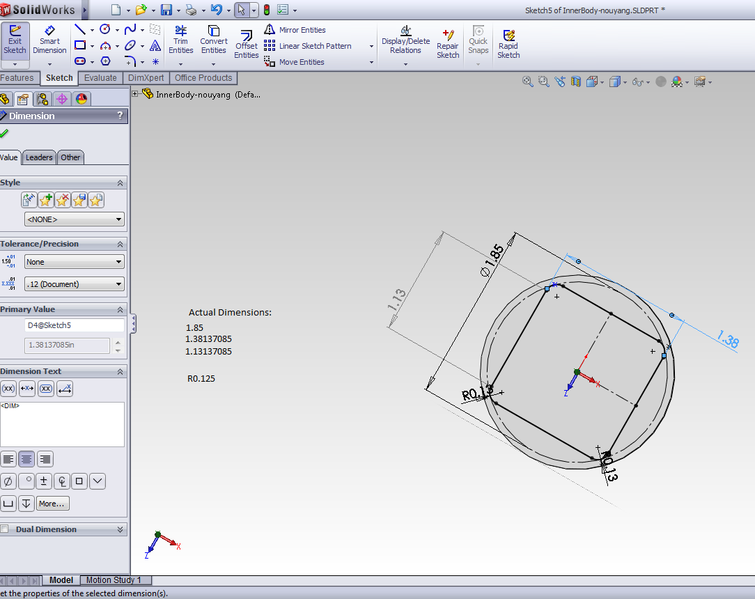
Me: if I want to make a board in eagle which fits inside a shape that I have a solidworks model of (I only care about 2d for now). It's pretty straightforward, so I can do the oldskool from x1 to x2 thing, but what if it were more complicated? Is the only way to do this export an image in solidworks and make a library part of it, or use some import_bmp script and trace over it in eagle, or something crazy? I guess the opposite is easier, show only the board, export image, import into solidworks, and trace it... What if I cared about 3d? Is eagle just have zero support for this?

Charles Guan:
Also, if you want to make a board of a certain shape in Eagle, it's a terrible pain. I was in fact just messing with this tool yesterday:
http://www.micromagicsystems.com/#/dxf-converter/4523812840
What I did was make a solid model of the plan of the board (sketch > extrude), then laid it out in a DXF drawing as if I were waterjetting it. If you just export a sketch as a DXF you have to exclude things like dimensions. The tool just imports every DXF entity into the .brd file on the Dimension layer.
Example board outline: http://etotheipiplusone.net/pics/moter/nicesensor3.png

If your board has internal slotting and stuff it will import that too.
John David Cranor:
cross platform one: http://fab.cba.mit.edu/classes/MIT/863.09/people/cranor/How_to_Make_%28Almost%29_Anything/David_Cranor/Entries/2009/11/16_Week_9__Output_Devices_files/DXF2SCR.C

In 3d, I have no idea, but check out this post:
http://sketchupdate.blogspot.com/2011/09/visualizing-circuit-boards-with.html
If only Sketchup were parametric...

You can poke the eagle file on github (https://github.com/nouyang/pov-yoyo > eagle-board > .brd) and see that I simply drew a rectangle starting at the origin and then set the x2 and y2 coordinates according to the 2d solidworks measurements. For my prototype, I didn't even end up using that board outline -- I sheared off the excess copperclad and sanded* the pcb where my shearing was file until the pcb fit inside, and then used rolled up masking tape to keep it in 'cos I sanding failed past pressfit tolerances.


* I was using FR1, not FR4, so sanding was fine.
FR1 versus FR4 copperclad:
The copper-clad we use in MAS.863 is FR1 Phenolic Paper, instead of the standard FR4 Epoxy Glass which is what you'll probably find on ebay if you search "pcb copperclad". Tiny particles of glass in the air make your lungs sad and result in increased cancer risk over time, so if you're milling boards or sanding them a lot you want to go with FR1. There are disadvantages which make FR4 preferred for Real Boards which are fine for DIY boards -- fr4 has less heat tolerance, delaminates easier, and cracks more easily -- see http://www.electronicspoint.com/paper-phenolic-pcb-t136758.html).
(For more info, see http://en.wikipedia.org/wiki/Printed_circuit_board;
for our fr4 supplier, see http://academy.cba.mit.edu/classes/electronics_production/index.html)

=====
Yes, I'm splitting my giant!update for today into 3 posts.
=====
(p.s. if you don't know what eagle is, it's free pcb layout software,  older version layout tutorial:  http://www.sparkfun.com/tutorials/109
schematic tutorial: http://www.sparkfun.com/tutorials/108
more resources (including eagle libraries) here: http://academy.cba.mit.edu/tutorials/eagle/eagle_resources.html,
and the list of parts for fab.lbr: http://fab.cba.mit.edu/about/fab/inv.html)

Thanks to Bayley Wang for being the first to show me how to use Eagle.

Saturday, November 26, 2011

PoV Yoyo, charlieplex+pov (attiny45, 6 LEDs/3 pins) research

[edit, 6 dec 2011, see update for semi-working-ness: http://orangenarwhals.blogspot.com/2011/11/pov-yoyo-update-v01-and-failcode-also.html]
board layout

mmm, fab'd a terribly board together for persistence of vision yoyo so now I can start on code.

charlieplex and basic hello world rgb led, c, attiny44 and 45 respectively

C cheat sheet

eagle brd and sch on github

charlieplexing with arduino libraries

hello world

olopede code (not charlieplexed)
https://raw.github.com/zbanks/muffinc/master/code/upov/main.c

tom's nanopov code (charlieplexed, in assembly)

ladyada code

gui gode, attin2313, has gui

assembly: avr instruction sets

led documentation

mmm instructables (attiny85, charlieplexing)

my own notes on make commands

==
real time clocks (for hat alarm clock)

Tuesday, November 15, 2011

more pov yoyo cost research

scale of 50 yoyos. project will be working on over the next month by dan fourie, laura shumaker, and I as a for-fun project spawned out of an idea my for-grades 2.008 team passed over.

functional parameters:
yoyo with integrated persistence-of-vision display

design parameters:
as of right now, for each side:
  • 5 LED display, similar to (josh gordonson and zach banks, fellow mit students) earlier work: 
http://olopede.com/media/img/micropov-hand.JPG
  • Goals: user-friendly and mod-friendly
  • Two buttons, high enough that can be accessed by pressing down on the clear thermoformed plastic cover over the circuitboard (similar to plastic water bottle in feel)
    • on/off power button(decided against the centrifugal switch designed by paulina mustafa, another classsmate, for their iron man arc reactor yoyo, because gives user option to operate pov-display without spinning the yoyo for a more stable display)
    • "change text displayed" button, and you can change the display by holding it up to your monitor ala http://fab.cba.mit.edu/classes/4.140/people/robert.hemsley/week8.html. This method means the user doesn't need to have special cables to change the displayed text, and we don't need a complicated / non-intuitive button interface.
    • http://tomscircuits.blogspot.com/2009/04/micro-pov.html
      http://parts.digikey.com/1/parts/389604-8-pin-test-clip-alloy-soic-15-923650-08.html 8pin: $14, 14pin: $17
      • if we order pcbs, can have holes for people to stick FTDI or ISP headers in, so people don't need to solder little wires straight to the microcontroller if they want to edit or update the firmware on the ucontroller (or make a clamp breadboard) or buy one of the clamp programmers 
      • can have another mode (hold down button longer?) to change the flicker rate, since we'll be using internal microcontroller clock which is RC and due to manufacturing variability only accurate to +- 10%
      • discarded option: right-angle button which sticks out side of yoyo. more complicated injection molds and I was worried if it'd be structural enough, since solder joints would be taking the strain. Seemed most likely to fail after repeated use.
  • PCB should snap fit in, so people can mill their own pcb's and swap out the pcb if wanted
  • Rectangular PCB should fit, so it's easier to panelize and easier for people to make their own board (can etch and shear off one side instead of having to have a mill and mill a circular board, although circular boards look cool .___.)
  • Ideally PCB is single-sided
  • run off a 3v button cell and contain a spare so people can go longer without ordering their own.
    • pcb serves as cell-holder, batteries should snap fit in to further simplify mechanical design
    • TODO not sure how batteries will be electrically connected to the board
  • for changing the battery / updating the firmware, top half of each side will be removable via a notch on the side
  • assembly: teach a microcontroller series and have people assemble two and keep one?
--maybe have a fourth state changing the flicker rate, in case a specific microcontroller's clock is off (on/off/text programming/flickr rate programming)

cost estimate: 
$4.30 for two attiny85's off of digikey, + shipping. || $2.96 for each attiny88 ($6).
cheap power-hungry LED, well.
Circuit: Shane's interior-routed circuitboard
(http://scolton.blogspot.com/2011/10/strobe-attack.html) cost ~$50 + shipping for 12 of them off of myropcb. Ladyada has a cost calculator for multiple suppliers and comments for each supplier: http://www.ladyada.net/library/pcb/costcalc.html
That's like $12 for each yoyo.

So uh... Maybe instead I will sink $80 into buying my own 1/64'' and 1/32'' spindles for the modela (each good for ~50 boards).
$2 per yoyo
ebay: $25 for 3x 9'' by 12'' FR4 board. Est.: our boards max 2'' diam, so 1.5'' square is 6x8 = 48 boards. So maybe $50 for 96 boards, or about
$1 copperclad per yoyo

Buttons:
75c ea @ 100 off of digikey. http://search.digikey.com/us/en/products/B3SN-3112P/SW262CT-ND/60835 (need 200). or ebay, 100 for $7 incl shipping. $14 / 50 = 30c per yoyo. but late shipping...! may be too late for the semester
$3 per yoyo.


phototransistor: 28c each @ 100.
$1.20 per yoyo.


10k resistor, 50kohm, 5x zero ohm, 4x 500 ohm, 1uF cap.
14c each @ 100, cap http://search.digikey.com/us/en/products/C3216X7R1H105K/445-1423-1-ND/569089
0.017 @ 100, 10k, 50k http://search.digikey.com/us/en/products/RC1206FR-0710KL/311-10.0KFRCT-ND/731430 http://search.digikey.com/us/en/products/RC1206FR-0749K9L/311-49.9KFRCT-ND/731890
0.01292 @ 250, total 400 needed, 500ohm http://search.digikey.com/us/en/products/RC1206FR-07499RL/311-499FRCT-ND/731891
total 500 needed
0.00676 @ 500, total 500 needed, zero ohm
(this is if pov circuit does NOT need any resistors etc. ala , these are all for voxel light-programming)  http://fab.cba.mit.edu/classes/4.140/people/robert.hemsley/week8.html
total = .14*2 + 0.017*6 + 0.013*4 + 0.007*5 = 0.469
About 50c per yoyo. these are all 1206 packaging!

CR927, 4 batteries each, 200 total: $22 http://www.ebay.com/itm/200-CR927-DL927-LM927-ECR927-KCR927-927-Cell-Battery-E2-/180756330972?pt=US_Batteries&hash=item2a15eab9dc#ht_2063wt_1163, 30 mAh, used in blinkies
44c ea. yoyo
(alternative: rechargeable ones, $1.44 ea 55 mAh TINY 6.8mm diam http://octopart.com/ms621fe-fl11e-seiko-8119587, with solder tabs: $1.29 ea 48mAh 12 mm diam http://octopart.com/br1225-1vc-panasonic-155413, $1.71 550mAh 23 mm diam http://octopart.com/cr-2354%2Fgun-panasonic-13183344
octopart search: http://octopart.com/partsearch/#search/requestData&q=lithium+battery&rangedfilters%5Boutput_voltage%5D%5Bmin%5D=1.5&rangedfilters%5Boutput_voltage%5D%5Bmax%5D=4.9945883802956885&rangedfilters%5Bavg_price%5D%5Bmin%5D=0.24250000000000002&rangedfilters%5Bavg_price%5D%5Bmax%5D=1.8412916540799584&start=10)


accelerometers 0.67 ea @ 100, http://search.digikey.com/us/en/products/MMA7660FCT/MMA7660FCT-ND/2186165, as used by
http://rucalgary.hackhut.com/2011/04/26/upov-with-better-firmware-pics-video-and-source/
Indeed mill-able on the modela -- http://www.freescale.com/files/sensors/doc/data_sheet/MMA7660FC.pdf 0.5mm gap, 0.3mm pad -- DFN package
25 mil pins (15.6 mil gap and 10 mil pad/trace) -- for modella, can achieve. aka 0.398 mm gap / 0.254 mm pad
$1.40 per yoyo
unless I figure out how to make accelerometers -- see http://www.dimensionengineering.com/accelerometers.htm, and the borked link is J. Doscher, Innovations in Acceleration Sensing Using Surface Micromachining http://www.analog.com/en/mems-sensors/inertial-sensors/adxl202/products/technical-articles/CU_ta_Innovations_in_Acceleration_Sensing/resources/fca.html
-- I'll just pre-program the flickr rate (and make it adjustable via the light-serial-programming protocol?)


total: $15 per yoyo + some digikey shipping costs, so close to $17 each if we count the aluminum molds and injection molding / thermoforming raw mats as free (due to 2.008). and of course free labor XD

=====
Previous research:
LEDs
If we use those super-efficient LEDs, they are 30c each if we buy 400 (50 yoyos * 8 = 400 LEDs).
(http://www.newark.com/jsp/search/productdetail.jsp?SKU=38K3409&CMP=AFC-OP&CMP=AFC-OP via http://octopart.com/partsearch/#search/requestData&q=Kingbright%20KPTD-3216SURC)
x8 = $3 (if we include shipping)
Total = $118 + $10 shipping (so upward bound of $130)
So, about $2.60 per yoyo
3V Batteries -- batteries are somewhere around $15 / 100 on ebay w/ free shipping, so $0.30 per yoyo)
 if we want them (I don't think we do, we should design this into our mold or PCB) holders would be $1.50 each http://octopart.com/partsearch/#search/requestData&q=cr2032

Microcontroller ~$1.50 each http://octopart.com/partsearch/#search/requestData&q=attiny25, maybe $10 for shipping, aka $1.70 per yoyo

Here is how the "spin-activation" would work:
http://cdn.makezine.com/make/2010/06/WP105LEDYo-Yo.pdf

So, at 50 yoyo's, we're looking at $6 each which is over our budget. However, I'm confident if we look a bit harder we can get the prices down to $5 each.

=====
Timeline:

Thursday: [everyone] finish the CAD for the molds
Friday: [nancy] check the dims / tolerances with Pat and Dave
Then CAM over the weekend Saturday, say meet for dinner on putz @ 5pm and then CAM (putzgiving is Sunday). Order electrical parts.
Hopefully mill / turn the molds over Mon - Wed before thanksgiving.
Finish electrical design -> gerber and programming over thanksgiving break and order pcbs if ordering them. by 26th
And injection mold / thermoform the week after (done by Friday December 2nd).
Assembly done by Dec 9th.

=====
PoV no accelerometer notes:
I got nanopov example working this weekend -- no accelerometer indeed means there's an optimum speed the display wants to be waved at. wave it too fast and the image gets stretched out, too slow and the whole image isn't displayed or it's super-squished.

Oh, Tom went over this in his blog post:
One downside of this design is that there is no synchronisation between movement of the display and the display output. So if e.g. you wave it left-right-left all output is mirror-inverted half the time. Also, there is no stable, repeating image as you would get from a constantly rotating POV.

Hardware sharing / versioning, recent startups

A good number of hardware (well, electrical) online version control / sharing startups have come up recently.
  • http://www.evilmadscientist.com/article.php/visdiff - thoughts on smarter diff for EE
  • http://upverter.com/ 
    • http://upverter.com/tour/eda/
    • (version control. has good snapshot features for both board and bill of materials. has embeddable schematics. has nets. based around github, so social) 
    • "Online electronics design. Includes schematic diagrams, design hosting, parts library, and GitHub integration. Free for public open-source projects"
  • http://solderpad.com/ 
    • http://solderpad.com/tour
    • (version control and online ee viewing, board and schematic embedding. less of a social feel) 
    • "SolderPad is a place to share, discover and collaborate on electronic projects." 
    • based off of github, so integrated
  • http://www.circuitbee.com/ -- no updates since october 2011?
    • (for embedding boards/schematics)
    • "CircuitBee provides a platform for you to share live versions of your circuit schematics on your websites, blogs or forums."
  • http://www.openhardwarehub.com/ 
    • (includes full hardware, not just ee, part sourcing) 
    • "The place to post and contribute to open-source hardware projects"
No doubt some form of open-source biology version control software will come into play soon too. But meanwhile the mechanical engineering side of things is looking a little bit neglected.

For online 3d model viewing, there are a few implementations, namely Thingiverse and 3dCADBrowser:
http://www.3dcadbrowser.com/preview.aspx?modelcode=3229 (has assemblies, it looks like) (no embedding)
http://www.thingiverse.com/thingiview:86385 (parts only, not assembled projects) (CAN be embedded!)
and a community around CAD:
http://grabcad.com/
another one, solidworks oriented:
http://www.3dcontentcentral.com/default.aspx

Tools / raw materials search: Maybe we should do our startup around this, for integrating into one of the hardware version control platforms. Octopart is doing it for EE; now lets get the meche side done too. Then we can really have full integrated open source products sharing+version control online, and then life will be awesome :)
If open hardware hub got popular enough (they allow "links" when you submit parts for your project), that would be cool.
[Edit 6 Dec 2011: I found a few search engines. See http://orangenarwhals.blogspot.com/2011/12/hardware-search-engines.html]

Some more research on the subject:
http://electronics.stackexchange.com/questions/8767/version-control-systems-for-hardware-projects basically says "use all the normal software version control systems" (none of which are made for visual diffing)
For some snark on circuitbee:
http://hardware.slashdot.org/story/11/07/26/183257/sharing-electronic-schematics -- so yea, circuitbee is not too useful
and some more snark on upverter / circuitbee for not making the extra effort to be open source themselves:
http://dangerousprototypes.com/2011/09/21/editorial-upverter-another-closed-source-vampire-exploits-open-hardware-for-ventrue-capital-pr-and-profit/
and
http://hackaday.com/2011/09/14/upverter-its-like-github-for-hardware/
I think actually both circutibee and upverter are awesome and people are just being paranoid. -^-^- look at the long responses all the posts got from the founders o.o

to check out: another online circuits project:
http://code.google.com/p/webtronics/

Saturday, November 12, 2011

China Makerspaces Visit Planning

I'm hoping to / planning on visiting Chinese makerspaces between end of term (12/19 for me, as I have not finals) and IAP (January 9).
[last updated: 11/24/2011]

http://hackerspaces.org/wiki/China
Shanghai

Shenzhen
  •   www.chaihuo.org, active as of november 2011
    • Saturdays, 14:00 – 16:30 (gcal sidebar)
    • ch.makerspace, g.com
  •   SZDIY (shenzhen diy lab) active as of today november
    • 聚会Every Thursday / 每周四 19:00~22:00
    • 答:Seeedstudio 是深圳创客空间(Chaihuo)的主要赞助商,Chaihuo与SZDIY目前达成协议在特定时间(每周四晚)免费提供聚会场地给SZDIY社区使用来举办固定聚会
    • szdiyadm, g.com
  • http://wikitravel.org/en/Shenzhen
Beijing
  •   http://bjmakerspace.com/ (both flamingoeda and gkfab have been subsumed by this, active as of october EDIT 11/24 active.)
    • meetings every Tuesday 20:00 to 22:00 (http://www.bjmakerspace.com/Event.html)
    • open every day (according to email correspondence 22 nov 2011)
    • http://space.flamingoeda.com/ (last update july)
    • GKFab (not alive?)
    • We have weekly meeting at Tuesday night, and workshops at weekend. The space is opened every day, and you may want send us a mail before you come so we can make sure there is some members in the space
    • bjmakerspace, g.com
  • yff -- not sure if it's actual makerspace looks corporate or spam. 
Guangzhou:
  • hackerspaces@gz (1 member?)
  • HTG (not active since 2010)
So looks like I should try to make Shanghai and Shenzhen, possibly Beijing although that's covering a lot of ground in a week (mmm transportation costs). Guangzhou ones seem dead, which is a pity since that's actually close to Shenzhen.

==
http://www.seeedstudio.com/blog/2011/10/16/first-open-hardware-gathering-in-china/
Ooh look! Someone I know is there! Star Simpson is apparently in China until January or so. And Maja Wichrowska (roomies shoutout!) is in Beijing for the semester. o.o Whoa. A lot of people I know are in China...
===
http://hackerspaces.org/wiki/Call-inJan 1st, 1600 EST
===
http://hackerspaces.org/wiki/Japan


  • kubotaa@tamabi.ac.jp (no response, dec 2011)
  • info@456.im (no response, dec 2011)
  • Tokyo hackerspace (contacted via form):
    • Tokyo HackerSpace has an open meeting every Tuesday night, from 7 PM. 
    • Unlike most other hackerspaces, our members have very little free time, and as such, the space is not in constant use. Our members have a key, and can come any time they like, but its hard to predict when that will be.
    • I would highly suggest that you join our google group and introduce yourself and your schedule there: http://groups.google.com/group/tokyohackerspace You'll have a better chance at finding what everyone is up to, and when they can meet up.

http://hackerspaces.org/wiki/China
? None in Taiwan nor Korea.
===
Visas and Passport Renewal
Proxy Chinese Visa service: http://ask.metafilter.com/95095/Visa-service-recommendations e.g. http://china.visahq.com/ (also does passport, also well-designed site)
Emergency Passport-ness: http://travel.state.gov/passport/npic/schedule/schedule_852.html

Boston-specific:
I found a local Chinese company helping with visa application:
国际文化旅游公司
Cambridge
617-868-3096
最便宜的机票+最优质的服务$170 total /1 year multiple entry。 If you fill out the form. Sounds reasonable. close to what they charge here.It is close to T. ~5 walking from T station. 2 stops from harvard (outbound).Go to the web site, fill out the file and print out. take 1 2x2 picture, the passport valid for 6 month and blank page .
经纬旅游 Boston 617-426-3123
===
electronicky shanzhai 山寨
http://www.bunniestudios.com/blog/?p=284
and also awesome book:
http://craphound.com/ftw/download/ which is a fantastic romp around gaming culture, economics, and unions.
more on shanzhai
http://www.tigoe.net/blog/category/environment/295/#more-295
more on shenzhen http://www.evilmadscientist.com/article.php/shenzhen
the linked article is account-walled so here is the article http://www.strategy-business.com/article/09315?pg=all&tid=27782251

===
personal

1Transportation FCU
55 Broadway
Cambridge, MA 02142
Driving Directions
 Send to Phone
ATM
Deposit-Taking
Surcharge-Free

1.16 mi


=== Options: personal tours. Or get MIT departmental backing (talk to Anne Hunter / Brandy Baker) for report publication, go in officially.

=== Oh hey look, someone wrote about MITERS in Chinese.
http://www.chaihuo.org/2011/10/19/%E5%88%9B%E5%AE%A2%E6%94%BB%E7%95%A5-%E4%BB%8Emaker-faire-%E5%88%B0mit-4/
"not the game, nor is it the job, just love" Thanks, google translate :)

===
update 2 dec 2011
according to David of shanghai's xinchejian, There are current 4 in China. OnionCapsule in Hangzhou is the first student lead hackerspace in the China Academy of Fine Art by a group of new media art students. They have a public performance scheduled on Dec 24. If visiting hackerspaces is one of the goal of your trip, I'd suggest you visit them at this event. It's crazy party and a lot of fun. 

Tuesday, November 8, 2011

Lasers and such (aluminum business cards, wood and paper etching, edge-lit acrylic signs, thermoforming

I'm proud to say that I've sunk at least 40 man-hours of other's people time into nyancat :)
(~150,000 views * 1 sec each / 3600 secs/hr  = 41.7 hours)
from 6:20am today (11/8/11) http://imgur.com/HnoAf
Makes me regret not thinking about watermarking my images (free publicity!). Thankfully, these are but brief lapses in my unfailing devotion to laziness.

Meanwhile, I've been exploring the joys of the lasercutter. I found some scrap wood sitting around the lasercutter and etched some of my best friend's art (shout-out to Alice Chung! http://the-crowned.deviantart.com/)
I didn't know what type of wood it was so I approximated:
material, lens, thickness, ppi, power, speed, description
aircraft plywood        2    1/8"        500    15%        80%        raster
aircraft plywood        2    .17        300    40%        3%        cut ~.17


I also want to make edge-lit signs and found some scrap acrylic. I checked out some real edge-lit signs, the ones used on the newer-style EXIT signs, looking straight up at them, and you can see the individual blips indicating a strip of LEDs. I thought they might have been using a fluorescent tube, which was my other though for lighting -- strip out a discarded scanner's tube and make a lamp ballast for it, then stick it over the acrylic. Todo: buy some nice strips of RGB LEDs. http://www.adafruit.com/blog/2009/09/22/making-an-edge-lit-acrylic-sign/ ~$7: http://ledshoppe.com/Product/led/LE5045.htm

this was .24'' thick acrylic:
ACRYLIC (clear)        2    1/2"        500    80%        50        RASTER, 1/32 inch
ACRYLIC (clear)    (tinted)    2    1/4"        500    100%        1.4        cuts through 1/4'' (.21'')

I'm sitting in the media lab shop right now helping a friend, Cathy Wu, make business cards for her imminent plane trip to some conference somewhere (_sigh_ smart people...). I was asleep in my room at 11pm when I heard a loud knocking, which turned out to be a hyper Cathy excited about cutting out business cards with the laser cutter :) I had some anodized aluminum let over from the waterjet clock class / Kevin Rustagi, so there we go.
Giraffe design courtesy of Laura Shumaker, another awesome friend.

Settings used:
METAL ENGRAVE    2    n/a        400    50%        10        (Vector) Engraves into most sheet metals. (incl. anodized Al)to confirm: "my impression was that CO2 bleaches the dye in the anodize coating, while YAG actually penetrates the anodize to etch the aluminum"

The 100 watt lasercutter is definitely not awesome enough to cut this out (we tried full power really slow speed high ppi and it looked to have cut to the same depth as the etching). Maybe the BEAM lasercutter? We settled on using the power shears to cut it out.

I also learned that one can etch paper without burning it up!
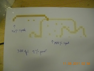
Construction paper    2    0.01''        500    6%        80%        etch; -- @100% speed, 7% min. to etch. @6%, 97% min. speed
thin cardstock -- 1mm thick
People online seem to be getting lighter engravings, though, and I can't figure that out! I tried all sorts of different settings for the construction paper and all I get is the burnt look. The cardstock I know for sure is white through and through and it also gives me this brown color. ??? I need to figure out this mystery:

http://www.epiloglaser.com/tl_paper.htm
Some very useful links:
Different materials at a glance, with examples (look at the dress under textiles! amazing)
http://lasercuttingshapes.com/page/materials
Everything ever about the Universal 100W CO2 laser and all the possible parameters:
http://www.inlay.com/cnc/laser/index.html
Supplier Acrylics, fluorescent (looks edge-lit without needing lighting):
http://www.usplastic.com/catalog/default.aspx?catid=442&parentcatid=443&clickid=searchresults

Ladyada's examples page:
http://www.adafruit.com/laser/
With more details here:
http://www.ladyada.net/library/laser/settings.html
What people charge for some lasercutting services:
http://www.tree-fox.com/laser-engraved-and-cut-business-card-110.html
And pumpkins! Plastic ones though. We have real ones on hall that I was pondering...
http://www.advancedwj.com/gpage.html1.html

In other news, my surface mount soldering skills have vastly improved with a touch of patience. These all used the: tin one copper pad | tweezer solder the component onto that pad so that it's straight | solder the other pad on | reflow the first pad. This seemed tedious to me in the past, but it actually goes pretty quickly and helps me place my components correctly (darn lack of silkscreening) since I'll go through and tin one pad for all the components.

I also printed tiny-to-be-painted-and-turned-into-earring nyancat:
This is the 3d printer:

Meanwhile in 2.008 we thermoformed for the first time. Here's the thermoform machine:
turned out pretty well, almost none of the webbing we were afraid of.
The machine is super-straightforward to use. I'll write it down sometime.
then you use the punch/die to cut out the part you want
some of the injection molded parts. The metal shim actually really affects the shrinking of the part, so our ring and body parts didn't press-fit together (both used a 3% shrinkage estimate). To be fixed!
Oh, and my food-grade silicone arrived. $17 for a lb off of amazon.
And I shopbot'd a new foam positive. But the silicone negative mold turned out fuzzy :/ with bits of construction foam attached:
Make lots of sacrificial cake until all the foam is melted away? I'm not sure. This silicone will stand up to 400F while the foam melts pretty easily (eg at the hint of a heat gun).

My vending machine coils arrived off of ebay. They definitely look like something I could make by hand.

Also, I learned that ftdi breakout boards are indeed substitutes for ftdi cables. See here for a cool look at what you can do with ftdi:
http://hackaday.com/2009/09/22/introduction-to-ftdi-bitbang-mode/
and some more about ftdi (e.g. vs. avr programmer):
http://www.ladyada.net/learn/breakoutplus/ftdifriend.html

Oh, for 6.131, my final project, some research:
Our normal 6.131 555 pwm generator will not work here. Servo "PWM" signals are very specific -- 2 to 4% duty cycle, 20msec period.
http://www.seattlerobotics.org/encoder/200106/16csscnt.htm
use a servo tester then:
http://www.hobbyking.com/hobbyking/store/uh_viewItem.asp?idProduct=17143 $5
or implement the circuit:
http://www.societyofrobots.com/robotforum/index.php?topic=13833.0


Also, turns out you can totally do diy soldermask (to mask the circuit traces you don't want to accidentally solder to):
http://retromaster.wordpress.com/pcb-making/ via http://electronics.stackexchange.com/questions/15792/diy-solder-mask-toner-transfer
and a product from seeedstudio:
http://www.seeedstudio.com/wiki/index.php?title=Solder_Mask_Ink

Thursday, November 3, 2011

Nyantart, "a strawberry poptart laser-engraved with nyan cat"

There's something about watching the media lab lasercutter etch nyancat onto a strawberry poptart that is soul-deep satisfying. Surely now the quality of my education is irrefutably worth my tuition...

meta-nyan! not yet recursive...
The most difficult part of this turns out to be not eating the poptarts long enough to make it from the grocery store to the lasercutter. I've wanted to do this for weeks, ever since I saw the Louisville hackerspace posting: http://www.lvl1.org/2011/07/15/new-laser-cutter/, but never made it to the lasercutter until last night. (and I'd never even eaten poptarts before the first time I bought poptarts with the intention of lasercutting them, hah).
that's the original inspiration on the right
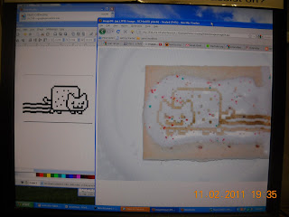
So, first things first, go to google images and find an image to trace (I used: http://thelemurblog.com/gallery/Nyan%20Cat.png). I tried to do my grid + draw lines method that I used with solidworks, now in GIMP, but ended up simply using select-by-color + bucket-fill-entire-selection.

this is the exact picture I used, if you want to laser-etch one of your own.
Then, play around with the lasercutter settings.

This is what I found to work (sorry for the terrible formatting):


MATERIAL:  LENS:  THICKNESS:  PPI:  POWER (%):  SPEED (%):  EFFECT (cut/etch)
Poptart            2    n/a        500    40%        80%        Light raster (will cut through sugar but not burn poptart)
Poptart            2    n/a        500    40%        50%        Medium raster (will cut through sugar and lightly singe poptart)
Poptart            2    n/a        500    76%        50%        Strong raster (will cut through sugar and darkly singe poptart)
on the universal laser x2-600 (co2, 100w).


I stuck it in Coreldraw on a 32x18'' bed to make sure it was placed correctly, then thanks to the Windows printer drivers, I simply hit Ctrl-P, set the settings, and printed it.


laser, do my bidding!
a few minutes and done~
Verdict: Still pretty tasty. The burnt ones tastes burnt, but both don't taste as bad as the lasercut sugar cookies.

light and strong rasters, side-by-side
reddit?
Haha, I put this up on facebook and not half an hour later it pops up on reddit:
http://www.reddit.com/r/pics/comments/lyktg/just_a_strawberry_poptart_laserengraved_with_nyan/

I wonder how it made its way there o.o?? I only posted it on facebook (this blog post was after the fact), so it's a little creepy.

FAQ
People wondering how they can make one of their own--
http://fslaser.com/40w-deluxe-hobby-laser-engraver-and-cutter
$2.5 to 3k 40W CO2 laser may be your best bet for cheap. It comes with caveats, though, see: http://hackaday.com/2011/04/14/buying-a-laser-cutter-from-china/ and other reviews online.
Probably a better idea to instead look at the list of hacker/makerspaces and contact your nearest one to see if they have a lasercutter you can use. http://hackerspaces.org/wiki/List_of_Hacker_Spaces
Alternatively, cut a stencil out of aluminum foil and blowtorch-singe or stovetop-pan-singe the appropriate parts. Although this tends to make a melty mess and I'm not sure how you would cut a stencil for a shape like this -- I guess connect some areas with thin bridges like they do for stenciled letters.
Although probably not recommended depending on what else was cut in the lasercutter, the resultant poptart is safe to eat -- it's the equivalent of a poptart which was super-toasted in some areas (all the laser is doing is dumping heat into some parts of the poptart, it's not dumping radiation or anything).
In fact, I stuck it in my hall's free-food table and both nyantarts were gone in an hour. :)

Oh, and more pictures here:
https://picasaweb.google.com/113942194695013581888/Nyantart#

Other nyancat shenanigans in the last month of two: (e.g. cutting it out of aluminum, making a mold for it): http://orangenarwhals.blogspot.com/search/label/nyancat


Todo
Next up: embed one of these suckers into the poptart and have it sing too!

http://www.instructables.com/id/Musical-Greeting-Card/

Then, after that, make a pressfit cookie nyancar. :) Like this, but with gingerbread (this is done in masonite) and with a nyancat center:


http://fab.cba.mit.edu/classes/MIT/863.09/people/mellis/pressfit/index.html